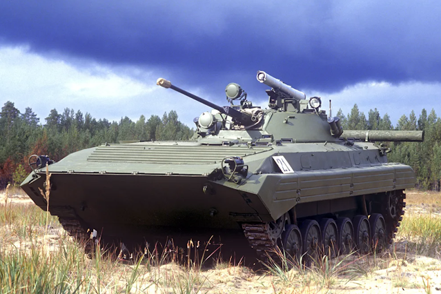
Ways to retain AFV mobility in harsh terrain based on traction and engine performance restrictions
The loss of an AFV's ability to move based on the traction characteristics of the engine/chassis is characteristic when moving vehicles on bases with low load-bearing capacity (weak soils).
The ability of the vehicle to move on terrain with a low load-bearing capacity is estimated using supporting patency indicators of AFVs.
Terrain passability is determined by the ratio of resistance forces to the AFV's movement, over a given terrain, its traction capabilities and coupling
When testing a vehicle's ability to drive on soft soils, it is expected to move without any additional support. In extreme circumstances, however, spare parts such as spurs, wideners, snow grabbers (duckbills), etc. can be used to enhance the vehicle's off-road performance.
Studies indicate that patency is affected by both the design parameters of an AFV chassis and the conditions that reflect the vehicle's movement. However, due to the requirements that must be met for the running part of the AFV and the overall layout and design of its systems and components, there is a limit to how much support patency can be increased by design parameters. The need to fulfil other requirements for the AFV also prevents significant changes to
At the same time, the value of the average specific pressure on the ground is most widely used as an indicator
Therefore, it should be assumed that cases of overcoming swamps or deep snow, as well as steep and slippery icy, clay, sandy and rocky ascents, reservoirs of small depth with a viscous bottom, etc., both short and, especially, of considerable length, can only
To minimize the time for preparation and overcoming obstacles, as well as dismantling and laying devices back on the vehicle, it is important to consider a new class of transportable means to increase the patency of the AFV. These means should be pre-installed or installed independently by the crew, without the need for engineering units.
Two types of devices can affect
The device is designed to improve a vehicle's cross-country ability. It consists of two drums with a special profile, one mounted on each drive sprocket (refer to Image 1). In addition, there are two steel cables, each measuring 80-100 meters in length, with an elastic synthetic cable at the front end that is 5-7 meters long and can handle 1.5-2 times more workload than the main cable. Each cable has a synthetic core at the end. The kit also includes rigging brackets and centring and guiding brackets that can be installed on the vehicle in advance.
The device is portable and lightweight, and some of its components can be mounted on the vehicle beforehand. It can overcome obstacles of any length as long as the cable is long enough. However, the device's ability to overcome steep climbs is limited by
When used on horizontal terrain, the length of the
The device works as follows: 2-3 turns of a cable are wound on the drum, the end of which is fixed to an object behind the obstacle, and the second is attached to a support vehicle, with which the cable is tightened to
The device provides the AFV
 |
| Image 1 1 - track; 2 - drive sprocket crown; 3 - steel cable; 4 - drum |
In contrast
.png) |
| Image 2 - BMP-2 equipped with the prototype device 1 - Drum; 2 - leading cable branch; 3 - Guide for directing steel cable |
For the experimental device, a steel cable (GOST 2688-80) with a diameter of 12mm and a breaking force of 92kN was utilized. The drum diameter was selected to be 615mm, which is equal to the diameter of the front drive sprocket. Also, the drum had a thickness of 48mm, and the cone-shaped working surface had an inclination angle of -12°.
During the experiments, tests were conducted on swamps and sandy inclines. When attempting to climb a sandy incline with an initial steepness of 25° and a length of 17.5m (as shown in Image 3), the tracks burrowed into the terrain, causing the angle of ascent to increase to 30°. The
.png) |
| Image 3 BMP-2 climbing a 25° sandy incline |
Tests have shown that the device can be used in various conditions without
The advantage of the device is that it optimizes the mode of interaction of the tracks with deformable terrain: slipping is eliminated and the pressure plot is levelled, as a result of which the depth of the track decreases, which, in turn, reduces the resistance load on the device.
The proposed method has an advantage over existing ones in terms of the length of cable used to overcome obstacles. It is practically
The device is suitable for overcoming obstacles of various types and has been tested with high efficiency in swamps and on sandy climbs.
To gain more traction when driving in soft terrain, another design can be used, as shown in Image 4. This design utilizes disks with crowns that are installed on the road wheels, aligned with their blades protruding beyond the width of the track. As the tank moves, the blades cut into the ground and create additional traction force without damaging the track.
.png) |
| Image 4 BMP-2 equipped with protruding blades (ground crawling blades) on 1st,3rd and 6th road wheels |
The disks have an asterisk shape with ground crawling blades that engage with the
 |
| Image 5 |
.jpg) |
| Image 6 Chart representing ground pressure based on the depth of a swamp. |
.png) |
| Image 7 Formation of additional traction force with the help of blade ground hooks |
A feature of the undercarriages of modern AFVs, which determines their behaviour in swampy terrain, is the large dynamic movements of the road wheels. With a relatively small stiffness on the elastic elements of the suspensions, along with a significant (up to 10% of the weight of the machine) value of the pre-tension of the tracks with the rubber-metal hinges, due to the need to ensure its sufficient stability in the outline, there is a significant change in the plot of loads on the ground under the support rollers when moving along such a section. Moreover, the heavier the traffic conditions, the greater this unevenness.
For instance, a T-72 tank moving through a 0.6-0.7 m thick snow cover at a temperature of +20C experiences a resistance force of about 8 tons. The working tension of each
 |
| Image 8 |
Studies have shown that when AFVs attempt to cross challenging terrain without prior preparation, they often get stuck due to the specific features of the AFV chassis and the terrain. The process of getting stuck goes like this: as the vehicle moves through the swamp, the height of the track increases from the first road wheel to the last, causing the vehicle to tilt significantly. As the road wheels move sequentially over the ground, the track under the last road wheel becomes almost five times deeper than the track under the first road wheel.
When the aft tip of the hull touches the surface of the swamp or another weak bearing base, the weight of the vehicle is redistributed from the chassis to the bottom. This increases the resistance to movement and makes it more difficult to gain
In summary, the redistribution of the weight of the vehicle from the chassis to the bottom leads to an increase in resistance to movement, requiring more traction force for movement. This causes an increase in the slipping of the track, the escalation of the ground by it, the redistribution of loads under the support rollers to an even greater extent, an increase in the track and the area of interaction of the bottom with the ground (swamp) until complete jamming and loss of the ability to move.
When the resistance to movement increases, the traction force decreases due to the decrease in the coupling weight and the destruction of the swamp crust. The tracks sink into less durable and more moist soil layers, which further decreases the traction force. The resistance to movement increases
.png) |
| Image 9 Process of an AFV bogging down in a swamp |
In addition, the size of the hull trim on the stern and the presence of corrugations, stamps, protrusions, and depressions of the hull
To overcome difficult terrain, one method is to rest the back of the hull on a temporary support placed on the surface of the area to be crossed. The support can be a single beam placed in the middle of the intended path of movement, a tree trunk, or a log. When the tracks sink deeply into the ground, the back of the hull can rest on the log and slide along it. This helps prevent further sinking of the hull, tracks and soil, which can be a problem in swamp areas. It's important to note that although the weight distribution changes, the upper layer of the swamp can compensate for some of the weight reduction
.png) |
| Image 10 Method application to reduce the force of resistance by eliminating points of interaction between the hull of the tank and the terrain 1 - bracket: 2 - log |
It is rather unclear, how the above-mentioned devices, the cable drum and ground crawler blades would work on much heavier vehicles like T-72/T-80 MBTs. Considering the large weight difference and overall track formation which occurs in softer terrain it would be difficult to find a suitable tree which can resist the force double or triple that of a BMP-2 along with having to create larger size ground crawler blades which can somewhat assist a 46-ton vehicle in swamp terrain.
- А.Л. Каменский, С.В. Рождественский, А.С. Смирнов, А.В. Доброхотов СПОСОБЫ ОБЕСПЕЧЕНИЯ ПЕРЕДВИЖЕНИЯ ВГМ В УСЛОВИЯХ ОГРАНИЧЕНИЯ ПРОХОДИМОСТИ ПО ТЯГОВО-СЦЕПНЫМ ХАРАКТЕРИСТИКАМ ДВИГАТЕЛЯ (ОАО «ВНИИТрансмаш», ОАО «УКБТМ»)


Comments
Post a Comment