This article is the first part of a set of articles covering the engineering and methodology used to create the T-80s filtration system, alongside aerodynamics to reduce airflow dust/sand contamination.
The T-80 MBT has been fielded in many climate regions. Desert climates pose a variety of variables that directly impact dust presence in the engine air filtration system. Variables include wind speed and direction, vehicle speed, depth and soil composition, air intake system design, and contours of the hull and turret.
Historical background:
Long-term trials were conducted in the southern Kara-Kum desert. It was determined that during 1970-1983, the quantity of dust present in the engine filtration system increased due to climate changes and weaker upper soil layers.
During the 1970s to 1980s, the Turkmen Canal underwent Soviet industrialization to build an irrigation canal and other facilities. This build-up of new infrastructure directly affected wind speeds in the area. In the early 1970s, average wind speeds were 2m/s-3m/s. In the early 1980s, average wind speeds were 6m/s-7m/s while achieving a maximum speed of 12m/s in the lateral direction. This change directly impacted dust and sand layer build-up, increasing the depth between 20cm and 50cm.
Technical analytics:
To further research the development of aerodynamics of T-80 tanks in related conditions, taking into account the wind speed, depth and dispersed composition of the soil surface layers, the T-80 underwent trials in aerodynamic chambers at the Central Institute of Aviation Motor Development (ЦИАМ). Aerodynamic tests were used to determine velocity plots and the presence of low-pressure zones, which can cause a build-up of dust in certain parts of the hull in variable directions of airflow. These results would provide comparative results to help assess the dust-proof effectiveness of parts.
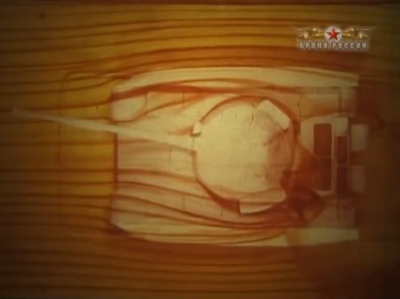
Video footage of a T-80 undergoing aerodynamic tests
Preliminary trials showed that simulated dust along the tank tracks and upper track guard would be thrown 2m-2.5m. Dust trails would deform downwards if the air stream entered between the tracks and the upper track guards.
According to the collected data, airflow separation points were identified at the front of the tank, near the turret's midsection, near the side skirts and the fifth and sixth roadwheels, and on top of the engine-transmission compartment.
Simulations were conducted in a wind tunnel by placing the tank at different angles against incoming airflow. The purpose of this was to determine dust and particle accumulation. Using a crosswind speed of up to 10 m/s and a flow rate of 5 m/s to 25 m/s, it was possible to simulate the movement of a tank at speeds ranging from 45 m/s to 72 m/s. It was determined that the turret roof had minimal dust accumulation, ranging between 1,5-2,5g/m^3. A 20° angle and 15 m/s wind speed were selected due to differences in wind conditions and tank movement.
 |
| Area of reverse airflow behind the turret with open hatches and mounted machine gun |
The affected zone of reverse airflow had a vertical height of 1,6m-1,7m from the engine deck. It was as wide as the hull and reached the rear mounting points for additional fuel tanks. There were also dust accumulation areas behind the MG mount and the open hatches, which created their own reverse airflow streams.
To determine if the speed of approaching airflow is correlated with the upper boundary of the reverse airflow current, the vehicle was placed in the air tunnel at 20° with an approaching wind of 5m/s-10m/s-15m/s, corresponding to the changes in a potential crosswind from 1,8m/s to 10m/s while achieving simulated vehicle speeds of 4m/s (14km/h) to 20m/s (72km/h). In addition to the crosswind, these figures would encompass all possible airflow scenarios. The test showed no changes to the upper reverse airflow boundary above the engine deck.
(2).jpg) |
Displacement of reverse airflow streams based on different crosswind angles.
No.1 20° crosswind angle, No.2 14° crosswind angle, No.3 7° crosswind angle |
Reverse airflow zones behind the turret shift into space beyond the downwind side when the tank is positioned at angles other than 0°. The magnitude of this displacement increases the steeper the angle between the vehicle's axis and the crosswind direction steepens. At the same time, the width of the dust flow increases. At an angle of 70°, the zone boundary from which dust flows enters the air intakes is at a distance of 30cm-35cm from the downwind side, at 14° at a distance of 45cm-50cm, and at 20° up to 70cm. These displacement changes can be observed in the image above.
It was established that airflow differences around the upwind and downwind sides were significant. The downwind flow created after the second roadwheel travels upwards to the upper reverse airflow zone behind the turret. This would cause a large influx of sand and dust particles inside the engine air filters.
To circumvent this problem, fording equipment was used as an elevated air intake system. The fording tubes were taller than the reverse air flow zone behind the turret, allowing clean air to flow into the filters.
.png) |
| T-80B uses parts of a fording kit with air intake tubes to minimize sand and dust interference |
Using fording equipment to reduce dust intake was not a standardized solution. Instead, a new air intake was designed, which had an elliptical shape.
A vehicle with the new air intake underwent similar aerodynamic tests. It was determined that air flowing in the reverse flow zone would circulate from both sides of the engine deck. This was due to the large front wall cross-section of the elliptical air intake. Due to the free space between the intake and the rear of the turret, a zone for dust and sand build-up emerged. The new air intake offered enhanced results due to it being above the cut-off section of the reverse air flow zone, but it made the vehicle's silhouette larger.
 |
| Airflow circulation around the air intake, with closed hatches and unmounted MG |


 |
| Drawings of T-72 aerodynamic features, created at the Central Institute of Aviation Motor Development (ЦИАМ). It can be observed that a reverse airflow pocket develops behind the turret above the engine filtration unit. This phenomenon is also present on the T-80. |
Further aerodynamics tests focused on reducing the upper cut-off section of the airflow current behind the turret. For this, the roof-mounted MG was removed. The purpose was to see the changes in the cut-off section height. This showed that the MG affected the airflow height above the turret. While the height of the reverse air flow current above the engine deck did not change, general airflow was now determined by the height of the air intake. If the air intake is marginally lower than the turret's maximum height, two different air zones of sand and dust will accumulate. The first zone is behind the air intake on the engine deck. The second zone appears in front of the air intake on the turret slant. To reduce airflow from the second zone, a metal plate was mounted at the top of the air intake at an angle of 12°-13° towards the rear of the hull. This resulted in a much lower intake of sand and dust from the rear zone.
This development led to the understanding that the air intake does not have to exceed the turret height while also retaining a low-profile silhouette. Several design proposals were presented to improve airflow currents above the tank's turret.
"The turret should have a section intended for mounting an air intake and be horizontally flat. If that is not possible, the turret should have a rear slant towards the intake, but not exceed a decline angle of 12°. Additional changes propose removing all objects from the roof that can raise the upper cut-off for the airflow current of large hatches and MG mounts. To optimize airflow, there should be a distance between the air intake and the rear turret slant equivalent to the width of the air intake."
The T-80U featured an air intake as part of its equipment, along with a fording tubes kit
 |
| T-80U air intake |
 |
| T-80U air intake with fording tubes |
While using aerodynamic tunnels to test airflow currents on the T-80 was a significant step in understanding the potential problems in harsh climates with "polluted" air, it wasn't the only approach to reduce dust contamination inside the engine.
The T-80 and subsequent modifications used dust prevention systems in the engine monoblock. It's also worth mentioning that the T-80U utilizes rubber flaps on the turret ERA and front part of the hull to reduce dust accumulation in major air currents travelling underneath and above the tank.
A topic covering the use of rubber flaps on T-80Us will come in the future.
Part 1

(2).jpg)
.png)


Comments
Post a Comment