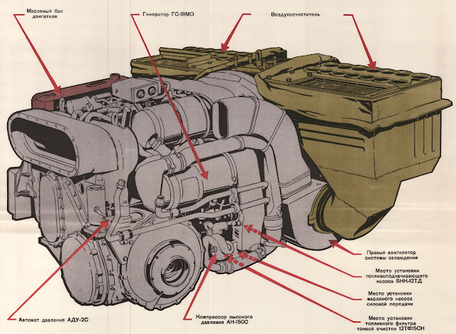
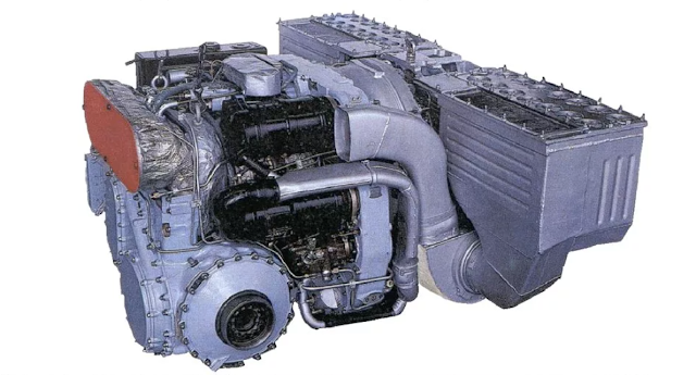
This article does not specifically cover individual filtration units but is a collection of features across several T-80 engine variants.
Since 1976, almost all T-80 variants came standard with gas turbine engines. Early T-80 variants utilized the GTD-1000T, the T-80B and its subsequent variants fielded the GTD-1000TF and the later production models of the T-80U used the GTD-1250. With each iteration, the HP (kW) increased to 1000 HP (745kW), 1100HP (820kW) and 1250HP (919kW).
The T-80 uses a monoblock-style engine developed in the 1970s by VNIITransmash "Предприятие п.я. А-7701", which means the engine block is mounted together with the air filtration system and other vital components. The air filtration unit is made of several parts assembled into a monoblock. The air filtration unit consists of 2 cyclone batteries, 2 oil cooling radiators and 2 cooling ventilators.
The 2 batteries contain cyclone filters. There are 14 cyclone filters arranged in a 2x7 pattern on each battery. One cyclone has a 90mm diameter. Cyclone filters use centrifugal force to push sand and dust particles out of the airflow. Under the cyclone filters, particles are collected in a collector compartment.
 |
| Cyclones spin at a high speed creating a centrifugal force that pushes dust and sand particles out of the airflow by directing the particles into a collector between a set of cyclones. |
The oil cooling radiators on each side are separated from the cyclone batteries and have no filters. The left oil coolant radiator is used for the engine's oil system, and the oil coolant radiator on the right is used to cool oil systems and hydraulic gearbox controls. Two ventilators push air through two air ducts to maintain high pressure. Both ventilators prevent excess dust and sand accumulation inside the filters. The third ventilator is located at the bottom of the filtration unit, which provides clean air to the air compressor, generator, and starter.
.jpg) |
| GTD-1250 air filtration unit. The GTD-1000T/TF filtration system is identical and does not differ in performance. |
Gas turbines can only operate efficiently when consuming clean air. This is why only the engine's main turbine assembly and vital core components receive clean air that passes through the cyclone batteries. Large dust particles under centrifugal forces are thrown against the cyclone wall. Purified air passes through the slots into the cone's inner cavity. The air travels through the bottom opening of the cyclones and enters a cavity for purified air. It is then supplied to the main engine assembly or travels through the bottom ventilator to vital components for cooling. Part of the air (0.22-0.27 kg/s), together with the separated sand and dust particles, is collected in the lower segment of the cyclones. From there it enters the cyclone battery dust collectors. The two ventilators remove air from the dust collectors.
The other parts of the engine receive air (0.7-0.8kg/s), which passes through the oil radiators, which act as partial filters. Sand and dust particles are mixed with air and sucked out of the collectors using both ventilators and leave the engine through the exhaust while cooling parts of the engine at the same time.
The rated average airflow of GTD engines varies by variant. The GTD-1000T is rated at not less than 3,8kg/s of air at maximum performance in nominal atmospheric conditions. This may also apply to the GTD-1000TF. The GTD-1250 across various sources may consume up to 4,6kg/s of air. This value can be explained due to the higher compression ratios of the compressors and turbines, which require more air.
 |
| GTD-1000T/TF and GTD-1250 air flow diagram. Red-black arrows indicate polluted air, red arrows indicate clean air and circulating air around the engine block, and black arrows indicate sand and dust particles. |
The filters achieve a cleaning rate of about 97.3%, enough for the gas turbine engine to function at maximum performance. The remaining percentage of particles end up in the main engine assembly and cause particle buildup on vital components like rotor blades and compressors. To avoid critical particle build-up the engine has several dust prevention solutions. This is done with high-pressure air valves and a pneumatic vibration cleaning system.
The high-pressure dedusting system is intended to clean the drive rotors on stage 1 and 2 turbo-compressors. The cleaning procedure lasts between 2,5 to 5 seconds.
 |
| Diagram of high-pressure dedusting valves |
The pneumatic vibration cleaning system is designed to remove dust deposits on the nozzles of the 2nd stage compressor of the turbine. This is done to avoid superheated dust particles from accumulating in lumps on the turbine housing and blades. The pneumatic vibrator operates at around 15000 RPM and creates a vibration frequency that does not interfere with the engine's functionality. The use of a vibration system depends on the engine state. After 3-5 hours of non-operation, the unit must be cleaned. While the engine is running, the system is intended to be cleaned every 2 hours.
 |
| Diagram of the pneumatic vibration cleaning system |
Part 2
References:
- Вестник бронетанковой техники, № 2, 1978 - "Воздухоочиститель для газотурбинных двигателей"
- Двигатель ГТД-1000Т. Техническое описание. МО СССР. Москва 1980
- Двигатель ГТД-1000Т. Серия плакатов
- Двигатель ГТД-1250. Серия плакатов
- Объект 219Р. Памятка экипажу по эксплуатации. МО СССР. Москва 1979
- Объект 219Р. Техническое описание и Инструкция по эксплуатации. Книга 2. МО СССР. Москва 1976
- Объект 219Р. Техническое описание и Инструкция по эксплуатации. Книга 1. МО СССР. Москва 1984
- Объект 219Р. Техническое описание и Инструкция по эксплуатации. Книга 2. МО СССР. Москва 1986
- Основной танк Т-80. Безмолвное возмездие / Иван Павлов, Михаил Павлов. Москва

.jpg)


Comments
Post a Comment