Posts

Showing posts with the label Theory

BMP-1 with prototype side skirts

Image
In the 1970's and early 80's, Soviet AFV engineers were tasked with developing countermeasures to a new emerging detection threat: radar systems used to detect ground-based targets. Existing solutions, such as radiation-absorbing paint, were no longer deemed effective. One of the theoretical solutions was to design mountable louvre-type sideskirts. The layout was arranged to create a wave-like pattern, with each slat strip to be placed vertically at an angle. With this type of layout, the panel would diffract incoming waves within a high degree of asymmetry, scattering the wave.  General design of the proposed louvre-style panel To confirm the theoretical results, full-scale measurements of the BMP-1's radar characteristics were done. One measurement without the louvre-style panels and the other with them. Only 70% of the new sideskirt was covered with louvre-style grills, which accounts for roughly 25% of the BMP-1's total side profile.  The average effective surface w...

Two-stage cyclone filtration system for T-80U

Image
 The deployment of BMP-1, BMP-2 IFVs, T-64A, T-64B and T-80 tanks with single-stage air filtration systems with an average purification rate of 99.8% confirmed their superiority over existing two-stage filter systems: lower weight, smaller dimensions and easier maintenance.  While the given purification rate of 99.7-99,8%, achieved by the T-80's cyclone filter array, is substantial, it does not meet industry standards set by OST V 3-2627-75.  OST V V-2627-75 is a Soviet and post-Soviet industry standard that dictates that AFV air filtration systems with cyclones have to meet necessary protection requirements against foreign debris that can get logged inside the cyclone cones, like pine needles, hay, dirt/mud, petroleum-based products, spent gas molecules, snow and others. This implies that the cyclones have to be protected by a mesh and or filter and can not be directly exposed to the environment.   A blocked cyclone array can severely reduce the air supplied to...

T-72/T-90 and T-80 engine cooling

Image
This article is a simplified approach to explaining how Soviet/Russian engines are cooled.  The T-72 and T-90 series of vehicles are equipped with standard V-84 and V-92 engines. Both engine types feature an enclosed liquid cooling loop with active air-cooling circulation facilitated by a fan.  The T-80 and its GTD series of engines, including the GTD-1000 and the GTD-1250, utilize active air and oil cooling for the turbine. DETAILED LOOK AT THE T-72/T-90 ENGINE COOLING LOOP T-72 engine cooling loop and layout The T-72 uses a closed liquid loop system to cool the engine and two oil lubrication tanks. Coolant heated by the engine is divided into three streams within the engine bay:  The main coolant stream is pumped into the radiators and cooled with atmospheric air, which is pulled into the engine bay using a ventilator. After passing through the radiators, the coolant enters the engine water pump. The second stream flows towards various components, such as the coils ...

T-80 MBT sound dampening panels - Part 1

Image
The goal of implementing sound-dampening panels on the T-80 MBT was to determine the possibility of mounting them in crewed compartments of the AFV, select materials that meet acoustic and operational requirements and evaluate their effectiveness in road conditions. A suitable design was to be developed by SPETSMASH (St. Petersburg) under the direction of V. M. Kirdey.   Image 1: Sound-dampening panels installed in the turret fighting compartment Image 2: Unfolded sound-dampening panel for driver's position  The dampening panels were placed in the following areas of the AFV and were composed of the following layers: The screens are comprised of various layers and materials in a certain order to achieve sound-dampening properties (the numeration of layers is counted outwards from the interior layer): Bottom of the hull between torsion bars: Povinol fabric, basalt fibre cardboard, knitting-stitching material, perforated fabric 500 (Cordura 500), PVC fabric, 2x knitted-needled ma...

T-80 rubber flaps - Part 3

Image
Over half a year ago, I promised to write an article about T-80 rubber flaps and their purpose, which would have completed the trifecta article collection: T-80 aerodynamic features and  T-80 MBT engine air filtration and dust prevention systems . This article builds up on the T-80 aerodynamic features topic and will conclude this series.  Unfortunately, I have come across zero primary sources, that directly mention the purpose of these rubber flaps, which makes it difficult to write an article with primary sources. There are 2 disputed arguments on this topic; one argument states that the flaps on the T-80s are meant to redirect airflow and reduce air contaminants like sand and dust from entering the engine. The other argument is that these flaps are used as additional protection to prematurely detonate HEAT warheads. I will discuss this topic by only talking about the presence of the flaps on T-80s. Firstly the rubber skirt, is present on the lower frontal plate of T-80s. I...

Soviet climatic simulation chamber

Image
Special climatic simulation chambers allow institutes to perform full-scale tests on AFVs by testing their components and performance in Arctic and subtropical climate zones.  The arctic climate chamber can simulate temperatures ranging from -15 °C to -55 °C, while the tropical chamber can achieve temperature ranges from 5 °C to 60 °C. Other varying climate factors can be simulated; air humidity and effects of frost and dew.  Data from the simulation is collected and processed using an automated computing system. Climatic chambers allow engineers to study the effect of various climates on the preservation and operability of vital parts. Engine performance and fuel efficiency are also studied since they are heavily reliant on surrounding conditions. The simulation of climatic zones also allows scientists to perform vital tests for microclimate research for the combat compartments.  I have decided to kickstart 2024 on this blog with a simple informative piece about Soviet c...

Comparative analysis of noise characteristics inside of tanks

Image
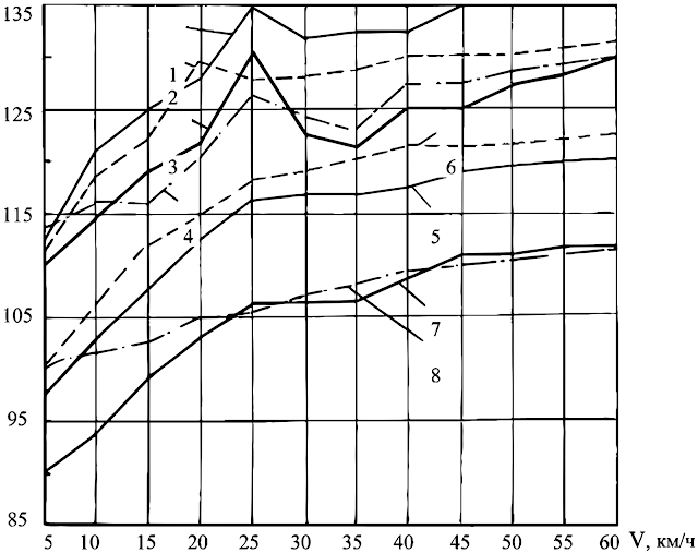
This is an introduction to noise characteristics of Soviet/Russian armoured fighting vehicles.  Vibrations, moving parts, and suspension all contribute to the internal noise level of a vehicle. These factors create oscillations that propagate through other modules increasing noise levels. To measure noise characteristics inside tanks, the driver's position and the turret crew's positions are measured separately. Units of measurement used for this are dB, dBA, octaves and Herz along with 2 different spectrums of sound; Level of sound pressure (LSP) "УЗД (Уровень звукового давления)" and level of sound (LS) "УЗ (Уровень звука)".  Unspecified variants of T-64, T-72 and T-80 and a T-80UD were chosen. The charts below show the dB/dBA levels for the different crew positions relative to the speed at which the tanks are moving. Tests were carried out on a concrete track. Lines 1-4 indicate LSP values for T-64/T-72/T-80 and T-80UD, while lines 5-8 indicate LS val...