Development of air-conditioning units for BMPs
Calculations showed that mounting an AC unit powerful enough to even out the 41,9 MJ/h heat generation would be impossible due to the needed size and weight. It was decided to create a unit with a cooling power of 25 MJ/h. The limited power of the BMPs generated prohibited the usage of the electric drive, to fully supply the unit with power.
Several designs were offered.
The 1st variant was a block design with a hydraulic drive compressor, ventilator compressor and air-cooling unit.
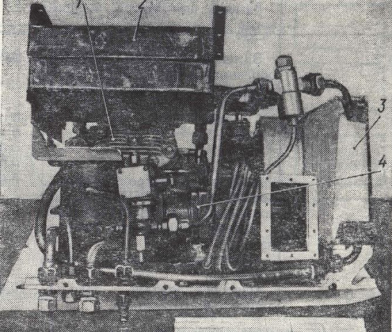 |
| AC Unit - Variant No.1 1 - Compressor; 2 - Condensator; 3 - air-cooler; 4 - hydraulic motor |
The AC unit was mounted inside of the combat compartment, to the right side of the turret, behind the engine compartment separator plate. The AC was directly connected to the engine and received power from it.
A regulated hydraulic drive provided an independent RPM link from the main engine to the hydraulic motor including the compressor and ventilator compressor.
The hydraulic drive system incorporated: a pump with variable efficiency rates, connected with a belt gear interlinked with the engine's driveshaft; hydraulic motor; safety and flush valves; lined filter; filter, pump and canister for the coolant recharge system; liquid cooler and tubing.
To increase/decrease the pump's efficiency a special centrifugal sensor was used. The hydraulic drive weighed 35kg. This AC variant differed from others due to its compact form and the usage of plate-shaped heat exchangers instead of tube-shaped heat exchangers. A 4-cylinder FU-4 compressor with an aluminium hull and a mechanical shaft seal was used. The compressor weighed 16,7kg. The main AC block weighed in at 118kg (without the hydraulic pump with hydraulic drives and tubing)
As previously mentioned, the mounting of the AC unit did not require major hull modifications and did not overcomplicate servicing the unit or the vehicle. On the contrary, integrating the hydraulic drive increased the vehicle's weight and also decreased the reliability due to the system working in parallel under high pressure.
 |
| AC Unit - Variant No.2 1 - Main air-cooler; 2 - control panel; 3 - condenser |
The problems that plagued the 1st AC variant were solved with the development of the 2nd variant.
A new design utilized an unsealed 2-cylinder compressor FV-5 (20 kg) with a cast steel hull and a mechanical shaft seal. To control the shaft an electric oil coupler was used. The 2nd variant utilized a similar mounting scheme. The compressor and electric oil coupler were mounted in the engine compartment and powered by the main engine. The condensation unit and air cooler were almost the same way as the 1st variant. Additional air-coolers were placed in air stream areas. This configuration optimized the airflow and cooling capabilities of all compartments. Additionally, the new variant offered the same simple mounting procedures but also offered 2 modes; cooling and ventilating.
Several tests were conducted in the city of Ashgabat with a BMP without thermal insulation but fielded with the experimental AC unit. During testing, the ambient temperature in the region sat stable at 37°C and with ambient air moisture of 26%. The first test was conducted with a turned-off AC. Temperatures inside of the vehicle were 7°C-10°C higher than the ambient temperature. The hull's temperature was 15°C higher than the ambient temperature.
With a turned-on AC, the internal temperature of the vehicle was much lower, reaching 33°C-35°C in the troop compartment and 29°C-33°C in the crew compartments. The AC unit reached 22,4 MJ cooling efficiency when running at 3000 RPM/min, cooling 1600m3/h of air, with a gradual temperature shift of 9°C-11°C on the air cooling units.
 |
| Crew compartment air-cooler |
After conducting tests it was obvious that vehicles with a similar AC design should be refitted with thermal insulation, especially around the roof segment of the hull, due to them heating up the most.
The 2nd AC variant showed better results but was also troublesome. The air consumption through the condensation unit was lower than anticipated and caused higher temperatures of the condensation process and as a result, lowered the overall air-cooling performance. A simple solution was thought of, a valve release system that would send out hot air outside of the vehicle. That idea did not get passed due to it requiring a complicated valve system and its production being complex.
Both AC unit variants utilized a control panel mounted directly on them. Instead, the panel was mounted to the closest crew member for easier use. It was noted that all tubing should be made out of soft tubing, which would ease servicing the unit and is more reliable compared to hardline tubing, especially when the vehicle traverses rough terrain.
After further revision, the FV-5 compressor made out of cast steel could be improved to reduce its weight and create a proper seal.
All the accumulated information about the 2nd variant was revised, issues were identified and all the gained experience was used to create more advanced AC units down the line.
Taken from: Vestnik 1986 No.1 - "Вестник Бронетанковой Техники 1985г сборник 1"


Comments
Post a Comment