Methods to camouflage AFVs
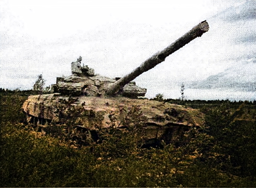
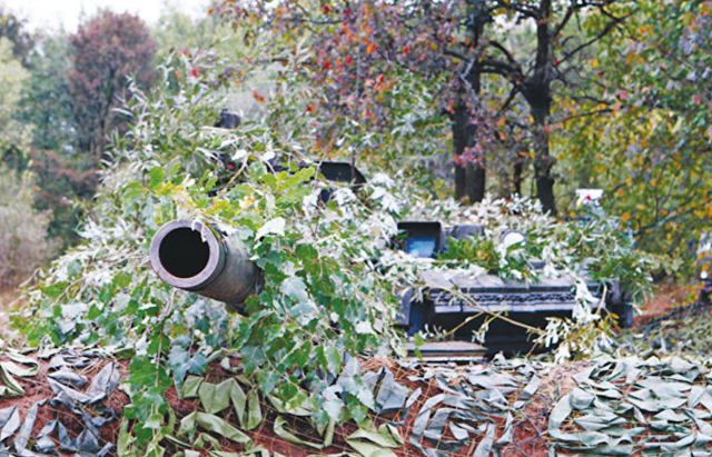
Camouflaging armoured fighting vehicles is an essential task to prevent the vehicle from being detected by enemy forces. Camouflaging can range from basic methods to more layered approaches which cover a wider spectrum of masking. Regardless of the method used, masking an AFV can apply to both ground and aerial detection, which operate in different spectrums of identification.
Camouflaging methods work in different spectrums against various detection methods. Optical detection can be combated with camouflage paint patterns or netting. Thermal imaging detection can be combated with paint or material that reduces infrared signature/reflection. Lastly, electronic detection (radar), can be defeated with methods consisting of several layers.
This article will cover commonly seen camouflage methodology present on Soviet and Russian AFVs.
Paint Camouflage
The most basic method is paint camouflage. Various paint schemes paired with specially designed camouflage patterns can be used to camouflage AFVs and make it more difficult to spot them using day-night observation devices. It is possible to achieve camouflaging by combining different techniques into one single design: colour differentiation between the primary paint coat and secondary paint spots, varying reflection coefficients in the infrared spectrum, and deforming the visible silhouette of a vehicle with a special pattern design. This is the more basic explanation of how this method is formed. Further information on camouflage paint can be found in this article.
Thermal insulation material for masking AFVs
Soviet engineers acknowledged the problem of lacklustre thermal masking back in the early 1970s. The most basic method of reducing thermal radiation on an AFV is to isolate heat sources and cover surfaces which radiate heat (up to maximum temperatures of 700C around the engine compartment).
Experimental work was carried out using a BTR. A thermal insulation layer of polyurethane foam (PPU-304) was applied to the inner surfaces of the hull and on the roof of the engine deck. The BTR's muffler and exhaust were replaced with an ejector-style muffler and exhaust solution designed by VNIITM. The general required results were to reduce radiant intensity (Watt/Steradian, Watt/sr))
| BTR View | Horizontal axis | Vertical axis | ||||
| J, Watt/Steradian | Jser/Jop | J, Watt/Steradian | Jser/Jop | |||
| Production Var. | Prototype Var. | Production Var. | Prototype Var. | |||
| Left side | 104 | 49,6 | 2,1 | 165,3 | 120 | 1,38 |
| Right side | 107,8 | 36,9 | 2,92 | 214 | 75 | 2,85 |
| Front side | 39 | 12,1 | 3,07 | 95,5 | 75 | 1,3 |
| Rear side | 266 | 23,7 | 2,83 | 261 | 93,9 | 2,78 |
| Parameters | Foam rubber | Parameters | Foam rubber | |||||
| PPU-304 | PPU-308 | Linear temperature decrrease in % at 70C withing 24 hours | PPU-304 | PPU-308 | ||||
| Volumetric weight, kg | 30-50 | 40-60 | I | I | ||||
| Strength limit under pressure kg/cm^2 | 1,5 | 3,0 | ||||||
| Water absobortion within 24 hours, kg/m^2 | 0,3 | 0,3 | Resistence against acids alkakis | Withstandable | -- | |||
| Strength limit under bending pressure nore more than, kg/cm^2 | 2 | 4,0 | Flamability | Self extinguishable, self burning capability duration after removed from fire, not more than 2 seconds | ||||
| Thermal conductivity coefficient no more than, kcal/m per hour C | 0,03 | 0,03 | ||||||
AFV foam coating camouflage
Water-organic foams have a wide range of masking capabilities, are easily formed and can be coloured to
 |
| Image 1 - External view of a T-80BV with foam coating |
 |
| Image 2 - Top-down view of a T-80B without foam coating |
 |
| Image 3 - T-80B without foam coating seen through thermal imaging channel |
 |
| Image 4 - BTR-80 with foam coating |
 |
| Image 5 - Comparison between a standard BTR-80 without foam coating on the left and a BTR-80 with foam coating on the right. |
Tank exhaust with reduced thermal signature for gas turbine engine
Tank exhausts are the most powerful source of heat emission and are largely responsible for unmasking AFVs in the IR spectrum. Reducing the level of heat emission of the exhaust presents significant difficulties, especially for vehicles with gas turbine engines.
Gas turbines operating at nominal power output levels produce exhaust gases which have temperatures of about 500C. The exhaust shutters on GTD exhaust reach temperatures of around 400C. A large area of the exhaust shutters viewed from the rear hemisphere creates thermal masking problems which cannot be solved with standard production exhaust devices which can dissipate heat. In addition, it is viewed that standard exhaust devices have significant aerodynamic resistance to exhaust gases and do not have sufficient armour protection, which eliminates threats like the intake of fragmentation bits entering the turbine.
A proposed design consists of an inclined armour plate, which rests on the side cheeks, one rotary blade and thermal insulation. The thermal insulation is placed between the blade and the plate on the outside. A distinctive feature of the proposed scheme is the separation of exhaust gas flows and cooling system air, where the cooling system air is exhausted upwards. The exhaust gases are diverted at a 40° angle downwards.
 |
| Proposed exhaust design with reduced heat signature properties |
The separation of gas and air flows incorporates the placement of air ducts above the exhaust pipe, due to which the temperature of the engine-transmission deck should decrease. The aforementioned armour protection is achieved with the installation of an inclined plate. The cooling system exhaust has a protective grate which protects against bullet penetration. Anti-radiation protection is ensured by traversing the blade which does not affect exhaust flow. Additionally when equipping the tank with fording equipment, the exhaust device can be hinged upwards and a bridging device is installed on the collar which directs exhaust gases up the fording kit tube. Overlapping armour plates over the air cooling system and significant thermal insulation material thickness, relatively low air temperature of the air cooling system (around 70°C), achieves acceptable thermal radiation characteristics in the rear hemisphere of the tank.
This proposed design provides a foundation for reducing thermal radiation on gas turbine tanks by normalizing exhaust values. Along with these changes it was considered that the new device also has improved aerodynamics with less drag for exhaust gasses.
Camouflage kits
 |
| Image 1: MKT-2L (summer) - MKT-2S (snow) - MKT-4P (desert) |
 |
| Image 2: Camouflage kit fragments |
 |
| T-90 fitted with Ternovnik |
References:
- Вопросы оборонной техники, Научно-технический сборник. Серия 7. Бронетанковая техника. Выпуск Но.4 (110). 1983 - Моделирование обнаружения БТТ средствами тепловой разведки, Г. А. Гуменюк
- Актуальные проблемы защиты и безопасности, Бронетанковая техника и вооружение Труды XIV Всероссийской научно-практической конференции Том 3, Санкт-Петербург 2013
- Маскировка объектов ВВТ Сухопутных войск пенными покрытиями
- Исследования оптических характеристик маскировочных материалов и покрытий
- Актуальные проблемы защиты и безопасности, Бронетанковая техника и вооружение Труды XVII Всероссийской научно-практической конференции Том 3, Санкт-Петербург 2014
- Военная Мысль, Но.2 Февраль 2021
- Министерство образования и науки Российской Федерации, университет ИТМО А.Ю.Королёв, А.А.Королёва, А.Д.Яковлев. Маскировка вооружения, техники и объектов. Учебное пособие. Санкт-Петербург 2015
- В.И.Климов, А.В. Кулешов, Тактика Часть 1 Маскировка. Учебное пособие. Рязань 2011
- Вопросы оборонной техники. Научно-технический сборник. Серия 20. Бронетанковая техника. Выпуск 26-27. 1972
- Patent: RU2492404C1


Comments
Post a Comment