Autoloading system for 76mm automatic cannon on light AFV
In the early to mid-1980s, the Soviet Union attempted to develop a 76mm automatic cannon fitted to fire telescoped ammunition to reduce toxic fume accumulation inside AFV crew compartments. The system was made to follow the existing AFV design philosophy, which was the limited application of extra mass and limited internal volume displacement.
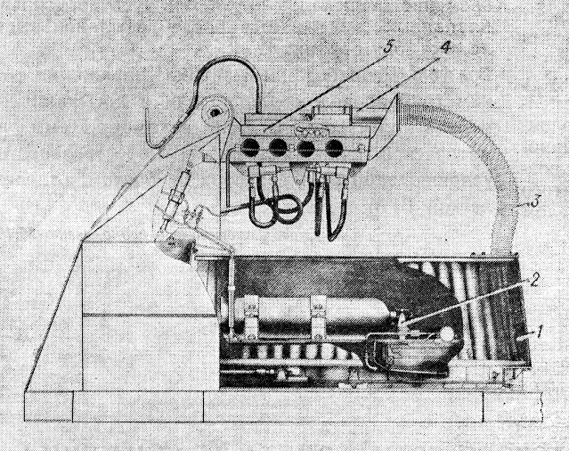
Along with the experimental cannon, an experimental automatic loading mechanism was created. This mechanism operated on pneumatics that supply telescoped rounds through a soft shell tube into the cannon breech.
The proposed display version of the loading system was made to fit the BMP-1's combat compartment volume and contains a mechanised ammunition rack with a 104-shell capacity, which is placed vertically with cylindrical cases for the telescoped rounds.
A breech imitator mockup was made to simulate recoil movement and breech operation. The initial design for the soft shell ammunition supply duct was made using flexible bellows with elastic membranes. The membrane petals would bend outwards and "hold" the ammunition during transportation to the breech. This design resulted in very unreliable performance. It was not possible to regulate the speed at which the telescoped rounds would move through the duct. The rate at which ammunition would be supplied could not be identified. The system also suffered major compressed gas leaks before moving shells, which reduced the efficiency of the pneumatic system.
A requirement was set that the speed at which the shell would be moved from the munitions rack to the cannon breech should be 5m/s, which could be achieved at an initial pressure in the receiver of 2,2*10^-1 MPa. Increasing the pressure further did not affect the speed at which the shells were transported. This was achieved with increased resistance of the flexible petals.
Further studies were conducted to replace the initial duct design with a continuous flexible elastic shell. However, initial reports showed several shortcomings in the design: a drastic decrease in the flow area of shells made using reinforced rubber with a casing thickness of 8-10mm, and slight bends in the duct would result in increased friction, slowing down the movement of shells.
A new duct design was created (copyright certificate No.19161 dated 08.02.1983). It consists of 3 parts: an outer bellows shell, an inner elastic shell and an elastic mass, filling the gap between them, made out of proposed material like polyurethane foam. The inner elastic shell retains the geometric properties of the duct's flow due to the use of curled walls. The outer shell with internal elastic mass filler, forms a bending line that adjusts to any elevation angle on the oscillating part of the 76mm automatic cannon.
.png) |
| Flexible pneumatic duct: 1 - internal elastic shell; 2 - external duct shell; 3 - rigid space filler (proposed polyurethane) |
Previously specified values for shell transportation speed were met with a new design reducing the amount of compressed gasses being lost, making it possible to reduce the pressure in the receiver to 0.5*10^-1 MPa. This new design was much simpler and more reliable.
It is established that an essential factor in increasing the efficiency of the pneumatic duct when the round passes through a thin-walled solid shell with an inner diameter smaller than the diameter of the ammunition is the formation of an annular micro-gap between the shell and the transported body. The movement of ammunition is accompanied by air "lubrication", while the leakage of compressed air into the volume before the round is transported.
During tests, it was conducted that travelling ammunition would cause disturbance of the free-floating curved duct. The amplitude of vibration would increase exponentially after every 3rd round cycle. This resulted in the rounds inside the duct bumping much harder against the inner duct shell and slowing down the movement. This was fixed with changes (patented document No.179990 dated 10.10.82) made to the rigidity of the outer duct shell. The improvement consists of lamellar chains located on the sides of a flexible pneumatic pipeline. The swivel joints attach to the outer shell of the duct with the use of clamps. The chain links have friction discs, limiters on how much the duct can bend and pneumatic diaphragm clutch actuators for friction discs.
Unfortunately, the fate of this weapon design is unknown. The original authors of the Vestnik publication claim that this system offered an increased rate of fire and improved combat conditions for the crew inside. This does correspond with the provided facts that the system lowered toxic gas fumes using a different type of round assembly. The system strays away from the conventional weapons fielded during the Soviet Union and would have offered a way to create an AFV intended to provide fire suppression using a high rate of fire. It is unknown what type of munitions were considered for this calibre and how they could have been used with such a system. It is also interesting how this autoloading unit would have been installed inside of the BMP-1 along with changes made to troop compartment capacity or completely removing troop transportation in favour of making a fire suppression vehicle.
Taken from:
- Вестник бронетанковой техники, № 3, 1985 - "АВТОМАТ ЗАРЯЖАНИЯ 76-мм АВТОМАТИЧЕСКОЙ ПУШКИ ЛЕГКОЙ ВГМ"


Comments
Post a Comment